Sv: Ombyggd E1820

1 och 2 ska bort.
3 ska skärmen lödas mot.
4 löds mittledaren mot, alltså utgående ur kontakten.
5 löds skärmen mot för dragavlastnings skull, denna blir potentialfri när komponent 1 och 2 tas bort.
Du är inte inloggad. Logga in eller registrera dig.
MobilaBredband.se © Störst på Mobilt Bredband sedan 2007 » Huawei » Ombyggd E1820
Sidor Föregående 1 2 3 4 5
Du måste logga in eller registrera för att svara
1 och 2 ska bort.
3 ska skärmen lödas mot.
4 löds mittledaren mot, alltså utgående ur kontakten.
5 löds skärmen mot för dragavlastnings skull, denna blir potentialfri när komponent 1 och 2 tas bort.
Notera att många av dessa "interna" antenninkopplingar bygger på kontakter som fixar ett fåtal inkopplingar innan dom är "utslitna" dvs förlusterna ökar.
Typiskt kan vara 10-100 inkopplingar. Egentligen är de tänkta som "testportar".
Kontakter som sitter åtkomliga "utifrån" är ofta specade för 5000 inkopplingar.
Inget fel att använda interna antennanslutningar men gör gärna anslutningen åtminstone semi-permanent!
1 och 2 ska bort.
3 ska skärmen lödas mot.
4 löds mittledaren mot, alltså utgående ur kontakten.
5 löds skärmen mot för dragavlastnings skull, denna blir potentialfri när komponent 1 och 2 tas bort.
Perfekt beskrivning! Kanske lika bra att klippa bort kontakten på kabeln jag beställt och löda fast den direkt om nu kontakten på modemet har så dålig kvalitet... Stelopererat innebär så klart mindre förluster... Kabeln skickades från Singapore den 15:e, får väl se om jag hinner få den innan helgen ![]()
hi All,
I write from Italy and I follow your forum since I bought an Internet key huawei.
I would like to connect an external antenna to main antenna connector but I have some trouble in soldering it onboard.
I have followed the instructions in the post of Andreas but I still can’t undertsand how to correctly solder the rg174 cable on the board. While it’s clear where the copper shield is soldered (on the previous antenna tip), I don’t know where the core conductor has to be soldered. can you please confirm me that the right place to solder the antenna is the one indicated in the picture attached? do I have also to remove the two component as indicated in the earlier post? is it possible to solder directly a connector on it or doesn't exist one that fit correctly?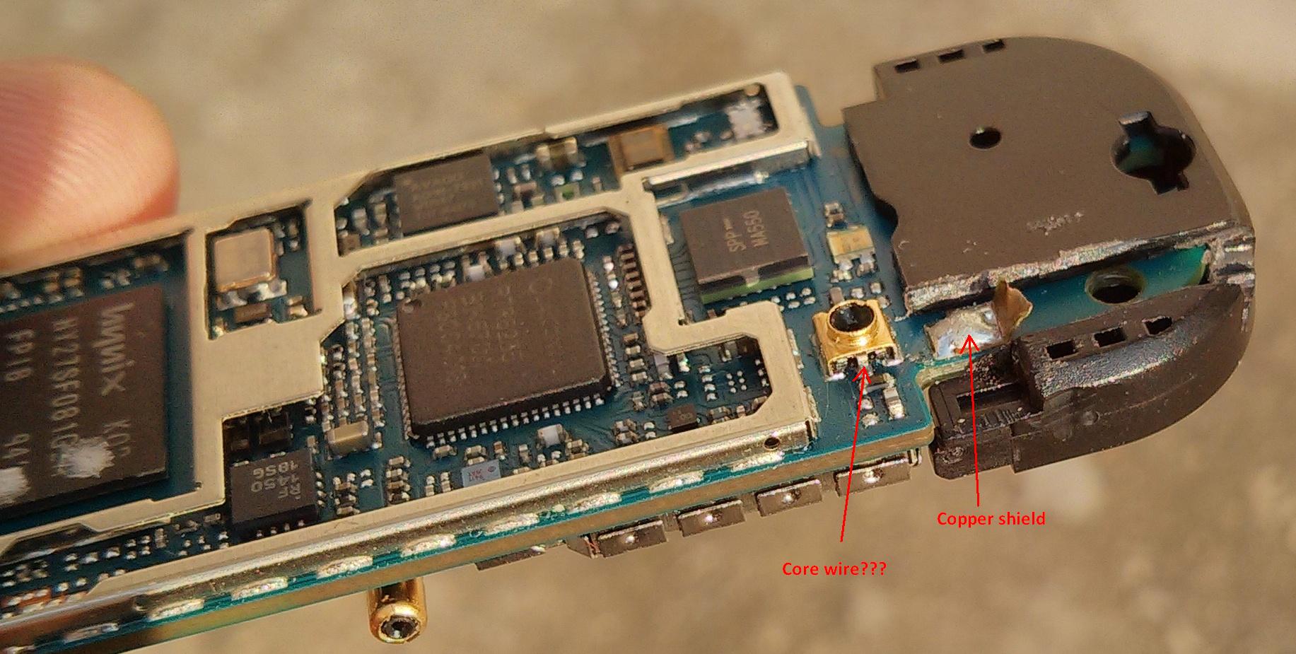
Ciao
Look at the photo in post #101.
Translation: Components 1 and 2 are discarded /They are there for impedance adjustment and not needed when the cable is attached/
You solder the screen of the cable to 3 /that's the outside of the coax connector/
You solder the core conductor of the cable to 5 /just like your own picture shows7
You also solder the shield of the cable to 6 to take the strain away /as you yourself suggest in the picture.
Furthermore, a glue pistol was used to embed the cable with plastic glue to fixate the cable.
Speriamo che tutto vada bene.
P.S. You can find a connector for testing purposes that fits but you shoul be aware that this type of connector will only function for attaching it 5-10 times. Thus it is better to solder the cable directly.
Sidor Föregående 1 2 3 4 5
Du måste logga in eller registrera för att svara
MobilaBredband.se © Störst på Mobilt Bredband sedan 2007 » Huawei » Ombyggd E1820